CATIA V5: How to Apply a Breakout View to Multiple Drawing Views
A Step by Step Explanation
A breakout view applied to any drawing view can be applied to multiple views (e.g. Isometric or Projection Views) without having to redefine the breakout perimeter and/or depth. The following steps can be used to apply a single breakout view to multiple drawing views.
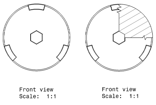
1. Apply and define a breakout view
Figure 1: Before and after a breakout view is applied to a drawing view
Figure 2: Breakout view depth definition
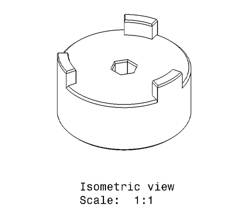
2. Create a new drawing view to which the breakout view will be applied.
Figure 3: Isometric view of the part
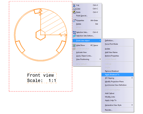
3) MB3 the border of the drawing view with the breakout. Go to ‘Front view object’, and select ‘Apply Breakout To’.
Figure 4: Selecting the ‘Apply Breakout To’ option
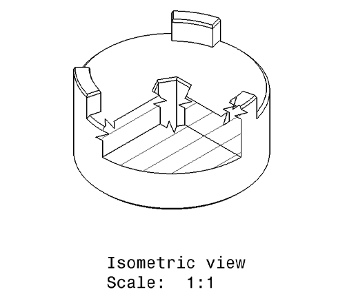
4. Select the drawing view that you would like to apply the breakout view to.
Figure 5: Breakout view applied to secondary drawing view
Discover more about CATIA V5.
