
CATIA V5: Propagation of Broken and Breakout Specifications
By default, any projection or auxiliary views generated from a front view with either a broken or breakout view having been defined, will not carry the broken/breakout view definition.
In order to propagate the broken/breakout view definition perform the following: Go to Tools > Options > Mechanical Design > Drafting > Layout > View Creation and then select Propagation of broken and breakout specifications.
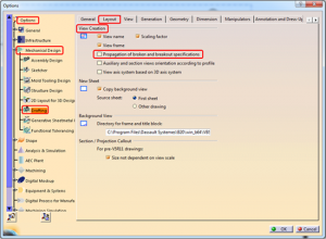
Figure 1: ‘Propagation of broken and breakout specifications’ settings

Figure 2: Before and After the ‘Propagation of broken and breakout specifications’ setting has been enabled
Discover more about CATIA V5.

